 Go to the Site IndexWelcome to the Lynx Repair Cook Book
October 30, 2011
Problems with a Lynx Camera can frequently be solved that do not require sophisticated test equipment or tools. None of the information provided here will be found in Yashica's repair manual. If you intend to buy a junker for parts, there is an outside chance that even within a specific model, that some parts may appear as slightly different or do not interchange. Copyright to the Text and Images is
enforced by me.
You may scroll the page [ recommended ] or click on a heading to jump directly to a paragraph. The topics that are dealt with include:
Adjusting the Silicone Photo Cell in the 1000 model:
Repairing Damage to the Lynx 5000e & 14e caused by Battery Failure.
Releasing the Battery cap
Removing the top plate, required for several repairs.
Freeing Seriously Stuck Batteries
Access to the Exposure Switch
Exposure Switch Test & Repair
Putting the Lynx IC Together Again
Removal and cleaning of the Finder Assembly
Access to the Finder Assembly
Release Stuck Frame Counter
Replacing the original foam light seals which deteriorate, causing many problems.
The Lynx 1000, model does not require a battery for it's Solar Powered silicone photo cell to read the exposure. The galvanometer needle read-out system seems sturdy enough, but the photocell sensitivity to light can weaken over time depending on storage conditions. Fortunately my Lynx 1000 still reads dead on when checked against a Sekonic reference meter.
Over time a number of inquiries have come in asking if the photocell sensitivity could be adjusted. The solution to this problem is to disconnect the 5k resister, and to bridge the circuit with a variable resister, [potentiometer] with a maximum value of 5k, and then to adjust this down until the exposure readout is correct. 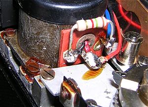 The value can then be read, and the 'pot' can be replaced with a fixed resister of the indicated value. Roy Laird [ Canada ] tried this fix at my suggestion as his camera was reading 3 stops down. In this case he replaced the existing resister with one of 2.9k. The meter now reads out correctly. Roy was kind enough to provide this image. It should be noted that the value of
the original resistor may vary from camera to camera, and of course the replacement resistor too, depending on the amount of correction needed. It should also be pointed out that Roy first of all cleaned the deposited film variable resistor surfaces and contacters in the shutter speed and lens aperture ring assemblies. These provide feedback to the system on the exposure being selected to null the meter correctly. See below for general guidelines in
removing the top plate for access.
The value can then be read, and the 'pot' can be replaced with a fixed resister of the indicated value. Roy Laird [ Canada ] tried this fix at my suggestion as his camera was reading 3 stops down. In this case he replaced the existing resister with one of 2.9k. The meter now reads out correctly. Roy was kind enough to provide this image. It should be noted that the value of
the original resistor may vary from camera to camera, and of course the replacement resistor too, depending on the amount of correction needed. It should also be pointed out that Roy first of all cleaned the deposited film variable resistor surfaces and contacters in the shutter speed and lens aperture ring assemblies. These provide feedback to the system on the exposure being selected to null the meter correctly. See below for general guidelines in
removing the top plate for access.
The one serious difference that divides the Lynx rangefinder cameras from the Electros, is that the "G" electronics are totally isolated from the camera body. In the Yashica Lynx 5000 and 14 series, the case is the conductor of the + positive, or in a limited number of cameras, the - negative electric current. There-in lies the seed of it's own destruction.
This section therefore deals in depth with recovering from a battery melt down
in the Lynx IC models.
I cannot over emphasize the importance of removing the battery from the camera whenever there is no film in it, suggesting that you won't be using it for a while. Further you need to keep the 2 batteries for the "e" version from making contact in storage as it is possible for them to short each other out.
When a battery leaks, the caustic fluid will travel along the electrical wiring path unseen below the insulation and usually cause a connecting point to another metal or solder joint to be literally eaten away. Because the entire body of the single and dual battery Yashica Lynx is an electrical conductor, the caustic battery fluid may deposit and be seen on any part of the camera.
The vent hole in the battery cap that was designed allow the escape of destructive gas, usually clogs up quickly, so the caustic fumes too will find their way throughout the body.
If the battery cap can not be unscrewed with reasonable effort, do not force it as you will only damage the keyway in the cap or the camera body by using pliers. The trick is to remove the top plate with the cap in place and then soak it in plain vinegar , not the gourmet variety. I first posted this some years ago as convenient source of a mild acid because we are not dealing with leakage from a car battery, which requires just the opposite, namely an alkali like a baking soda solution.
Parts that Keep the Top Plate Down: The removal of the top plate is required to gain access to the battery compartment, clean the viewfinder, and other procedures. Use of a magnetized screw driver will help to hold onto the screws, and ease their later replacement. Keep all parts in a dish that will not tip over. If you allow any of these tiny items to fall off your work top, you may never find them again! Keep track of the sequence of the parts as you remove them. Talking into a tape recorder is a good idea.
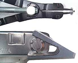 The first step is to remove the Film Advance Lever. The safest way to remove this without scratching up the fittings, is the use of an Adjustable Snap Ring Pliers. These pliers are sold at Auto supply and hardware stores and are used to handle "C" clips and should come with a set of several size points, both straight and angled. The points are interchangeable and the set required is .039 inch. Note the large head and tiny thread of this screw being held by the
tool in the image. Too much force can easily snap the head off the stem. If it won't budge, apply a soldering gun to the screw head for a minute or so to break the bond. Turn counter-clockwise to remove the pin head screw. Little effort is required.
The first step is to remove the Film Advance Lever. The safest way to remove this without scratching up the fittings, is the use of an Adjustable Snap Ring Pliers. These pliers are sold at Auto supply and hardware stores and are used to handle "C" clips and should come with a set of several size points, both straight and angled. The points are interchangeable and the set required is .039 inch. Note the large head and tiny thread of this screw being held by the
tool in the image. Too much force can easily snap the head off the stem. If it won't budge, apply a soldering gun to the screw head for a minute or so to break the bond. Turn counter-clockwise to remove the pin head screw. Little effort is required.
The next step is the removal of the rewind knob assembly. Use a wedge to get a good grip without damaging the finish of the knob. The image shows a homemade wedge cut out of a scrap of plastic, but hard-wood can serve the same purpose.
A strip of rubber from a tire tube has been glued to the inside using crazy glue [cyanocrylate]. Another option is to lift the retractable wind knob handle and remove the tiny screw that is holding it in place. A small flat spring that keeps the handle folded down will also come loose. Save these parts carefully. You can then insert a bar in the resulting slot and use that to turn the rewind knob assembly. Next open the rear door of the camera, and insert a firm strip between the fork of the shaft that engages the film cassette. Try to find something that will not scratch if it reaches down too far. Holding the shaft in place firmly, unscrew the rewind knob counter-clockwise. There is a small washer between the rewind shaft and the knob. Tape it to the knob when it is
removed for safekeeping. Take note of the sequence of all the parts as you remove them in the next steps.
Now you are ready to remove 1 screw from each end of the the top plate. There are only 2 phillips head screws which secure the top plate of the Lynx. Do not use a 99¢ store tool for this. Use a precision #3 Phillips Screwdriver [2mm] . This work should be done where there is no chance of the removed screw falling down and disappearing. If you have difficulty loosening a screw, do not
use brute force which can damage the screw head, screw driver or both. Apply a soldering gun at high heat directly on to the screw head for about a minute and try again.
Removing the Top Plate of the Lynx 5000 & 14'E' versions: The top plate is now ready to be lifted off the body. Apply gentle even force and rock the cover plate very slightly left to right and end to end. A layer of cement is holding the top plate to the body around the edges which will give way eventually. A little rubbing alcohol applied around the seam with a cotton bud may help. It is important not to push up too hard because the internal
leads from the light sensor [ Cds cell ] that is attached to the top plate are extremely short and you want to avoid tearing them loose if possible. In the event that you cannot loosen the top plate that way, you can use a piece of wood or plastic and apply it to a part of the exposed edge of the case and gently tap up on the block with a hammer. Use restraint. You do not want the
top to pop off suddenly with enough force to tear the wiring. If you tap the case up with a screw driver you WILL cut into it and ruin the camera. Some additional images can be seen in the 'Rescue Guide' on this site
Your work surface should be protected by sheets of newspaper or some such, because as the case comes free from the top, small bits of green caustic battery residue may fall out. Clean up and prevent this stuff from contacting anything. You will also notice that a foam gasket is sitting on the stem of the rewinds shaft. This will have partly or totally disintegrated. Carefully remove all traces of this.
Once the top plate is removed you can rest it on a small platform to ease the strain of the wiring connections to the body. At this point it is best to release the Photo Cell from the case. One offset screw to the right of the assembly is all that is holding it in place. It may come apart as a single unit, but be prepared for it to come loose in four small parts, the lens, black ring spacer, extremely small round spring and the Cds cell itself.
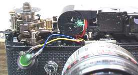
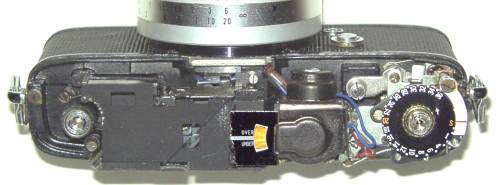 The Yashica Lynx 5000 & 14 have no components attached to the top plate that require wiring, so it is a little bit more convenient to remove without the worry of tearing a connection loose. As you can see in the image of the 5000 with the top off, the photocell sensor is mounted to the camera body. The simplyfied null meter is much less confusing than the meter on the Minister D and uses feedback from resistors within the ASA / ISO setting, lens aperture and shutter speed rings to indicate correct exposure.
Removing Stuck Batteries: Cotton buds dipped in vinegar can be used to remove any signs of the green plague where ever you spot it. Solid specks can sometimes be best picked up with scotch tape. The battery can be removed [ 2 in the E series ] and the extent of damage to the holder assessed. 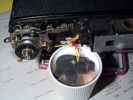 In the event that one or more batteries will not freely fall out of the battery compartment, do not use force. A battery can fuse to the flat spring contact at the bottom of the holder with such tenacity that digging the battery out will destroy the delicate spring contact.
In this case loosen the two screws holding the battery compartment and the dip the whole assembly, batteries and all into a beaker of vinegar. Bubbles will be released showing that the chemical process is working for you. After an hour a change of vinegar may be required. This is the time to clean up in the area of the case that would normally be covered by the battery holder.
Clean the battery compartment and screw-on cap using vinegar applied with a cotton bud. More extensive contact cleaning may be required. See the 'Rescue Guide' on this site for tip on that. Even a small tug on the white wire to the far side of the battery compartment may separate it from the solder joint if it has been attacked, usually readily visible as a green deposit where this
occurs. If good connections exist, put the batteries in the holder and connect the plus end to the body. You may need a helping hand for this. If you do not have the correct fresh batteries, use the AA or AAA batteries in your TV remote temporarily connected in series, Now press the exposure meter switch and look at the over / under light indicator attached to the left side of the
battery holder. Move the exposure rings on the lens. At some point one or other of the lights should be visible. If the lights do not come on and you are positive that you have a good electrical connection to the body, follow plan B.
Remove the bottom plate of the camera. Be careful, a spring and small washer associated with the door-open release plunger will be free to fall out and get lost. Plan B. In this case no battery power is required. The use of an Ohm Meter or continuity test device is required. The voltage applied by the device should not exceed the voltage of the camera battery. Attach one Ohm meter lead
from the white wire connection to the battery holder and the other to the white wire on the small circuit board on the bottom of the camera. Press the Exposure Switch button on the front of the camera. If the switch can now control the continuity, it is working, and only the wiring to it from the battery holder was defective.
In the event that one or more batteries will not freely fall out of the battery compartment, do not use force. A battery can fuse to the flat spring contact at the bottom of the holder with such tenacity that digging the battery out will destroy the delicate spring contact.
In this case loosen the two screws holding the battery compartment and the dip the whole assembly, batteries and all into a beaker of vinegar. Bubbles will be released showing that the chemical process is working for you. After an hour a change of vinegar may be required. This is the time to clean up in the area of the case that would normally be covered by the battery holder.
Clean the battery compartment and screw-on cap using vinegar applied with a cotton bud. More extensive contact cleaning may be required. See the 'Rescue Guide' on this site for tip on that. Even a small tug on the white wire to the far side of the battery compartment may separate it from the solder joint if it has been attacked, usually readily visible as a green deposit where this
occurs. If good connections exist, put the batteries in the holder and connect the plus end to the body. You may need a helping hand for this. If you do not have the correct fresh batteries, use the AA or AAA batteries in your TV remote temporarily connected in series, Now press the exposure meter switch and look at the over / under light indicator attached to the left side of the
battery holder. Move the exposure rings on the lens. At some point one or other of the lights should be visible. If the lights do not come on and you are positive that you have a good electrical connection to the body, follow plan B.
Remove the bottom plate of the camera. Be careful, a spring and small washer associated with the door-open release plunger will be free to fall out and get lost. Plan B. In this case no battery power is required. The use of an Ohm Meter or continuity test device is required. The voltage applied by the device should not exceed the voltage of the camera battery. Attach one Ohm meter lead
from the white wire connection to the battery holder and the other to the white wire on the small circuit board on the bottom of the camera. Press the Exposure Switch button on the front of the camera. If the switch can now control the continuity, it is working, and only the wiring to it from the battery holder was defective.
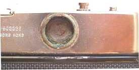
If you can not get the switch to work, the battery fluid will have destroyed the wiring to the switch or the spring inside it, that is part of the circuit. It will need to be replaced. A green corrosive deposit where the white wire connects to the back of the battery holder as shown, and this is a tip off that the wiring to the switch needs to be replaced and the spring within the switch itself is probably eaten away. Even a tiny amount of green around the chrome Exposure Switch, as readily seen from the front of the camera usually confirms that the switch is in need of repair and rewiring.
Access to the Exposure Switch:. To gain access to the exposure switch, the lens plate must be removed. The Top and Bottom cover plates of the Lynx are taken off. The next step is to find a knife which is not too sharp, so you don't cut yourself or the plastic skin covering. 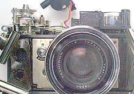 Carefully begin peeling back the skin around the lens. Use a cotton swab to moisten the leading edge with isopropyl rubbing alcohol to help things along. It is possible to start at the straight edge of the camera sides, but if you slightly disfigure the skin it will show badly when it is cemented down again.
On the other hand the curve around the lens is more easily stretched into place invisibly when you are done. I started at the bottom which is even less noticeable....just in case. Your Choice.
Carefully begin peeling back the skin around the lens. Use a cotton swab to moisten the leading edge with isopropyl rubbing alcohol to help things along. It is possible to start at the straight edge of the camera sides, but if you slightly disfigure the skin it will show badly when it is cemented down again.
On the other hand the curve around the lens is more easily stretched into place invisibly when you are done. I started at the bottom which is even less noticeable....just in case. Your Choice.
As you progress by slowly moving back the skin, you can keep the loose end out of your way by attaching a file clip to it as shown. Continue to peel back the covering on both sides until you are passed the edge of the lens mounting plate to the body. Do not pull the skin back further as the remaining portion will
keep you in alignment for re-attaching it later. A good glue stick may be all that is required to re-attach the skin later as it's surface will remain tacky if not exposed to dust. Note that the skin is factory cut out to fit around the logo and the Exposure Switch. Now remove the 2 screws on each side of the mounting plate and gently pry up on the edge of the plate with a small screw
driver until the plate lifts. Gently lift the plate a short distance and note that there are wires attached to the lens assembly from the body.
Exposure Switch Test & Repair: With connections to the exposure switch now directly accessible, the continuity of the switch is readily checked with an ohm meter by-passing all the wiring.
Failure at this point requires the removal of the switch and the replacement of the spring inside it that acts as part of the circuit conducter. The switch can be seen on the right with the PC socket located below it. As small as the detail is, the corrosion at this point can clearly be seen as a speck of green at the solder joint of the upper wire connection.
The wiring will have to be replaced. The best source for a pliable replacement of a suitable gauge that I have found is stranded telephone wire.
First however, the switch needs to be released by removing the two screws holding the nylon retainer in place. This reveals the cup that holds the push button and the spring that makes the connection in the circuit. One end of the spring is straight and passes through the retaining cup and the nylon plate
that holds it in place.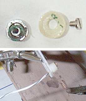 In the closeup image you can see the damage done by the caustic release of a leaking battery to the spring as seen coiled around the shaft of the chrome plated pushbutton, and some residue left on the nylon piece, particularly at
the hole that the end of the spring had passed through.
In the closeup image you can see the damage done by the caustic release of a leaking battery to the spring as seen coiled around the shaft of the chrome plated pushbutton, and some residue left on the nylon piece, particularly at
the hole that the end of the spring had passed through.
I was fortunate in finding a spring that was of a suitable diameter and tension in a package of assorted hardware that I bought years ago. If you rummage around you should come across a suitable spring. Before cutting the spring to length straighten out several coils to form the pig tail to which you need to
solder a wire lead.
The lower image shows how to hold the end of the pigtail with a heat sink in order not to kill the resilience of the spring. Note that the pig tail of the spring must pass through both the cup holder and the nylon retainer before you solder to it. To the right in the image a newly formed replacement spring is displayed held in an alligator clip. This is a still just little over length at this point.
Putting the Lynx Together Again:. With the battery switch cleaned and replaced, solder one new lead to the switch that goes to the battery holder. Leave the other end free. Double check to see that the shutter release rod and spring are clean. Some of the corrosive
gunk from the switch assembly sometimes falls off onto these parts or in the general cavity area.
Turn the lens focussing ring to infinity. This gets the yoke that will engage with the rangefinder lever, as far back as possible. Bring the lens mounting
plate in position, resting the bottom edge on the camera body. Dress all the wires except the lead to the battery holder under the round lens shield, and then guide those going to the top of the camera, up through the keyway slot on the body. Drape the loose white wire from the switch up above the shutter release lever on the lens itself and up through the pathway with the other
wires going to the top.
The shutter is wound by a hollow shaft on the upper front of the camera that has a small slot across it. This engages with a rod that has a pin at it's end mounted on the lens. Turn the pin on this end by gently pushing the pin with a toothpick or small screwdriver, until it lines up with the keyway on the camera. Bring the mounting plate to the camera while flipping down the shutter release flange that engages with the lens activator and make sure that it is
above the lens lever. A little juggling and a lot of patience is required. A bit of luck won't hurt either. Make sure that as the lens mounting plate seats to the camera, that the focus yoke on the lens engages properly with the rod on the lever of the rangefinder. Now screw the plate down, but don't put the skin back down until you have double checked that everything is working. Draw up the slack from the white wire that will attach to the battery holder. Place the shutter wind lever parts temporarily in place and wind the shutter. Press the release to confirm that the shutter fires and wiring is not hanging it up up. Only then should you cut the white wire to length and solder it the battery holder.
As you turn the focus ring you should see the mask move diagonally. It's the piece that has the frame line cut out in it. If the internal optical elements
move, but the frame-line does not, the rangefinder must be removed.
Removal & Cleaning of the Finder Assembly:To gain access to optics as well as the 2 screws which attach the finder
assembly to the body, the top cover of the finder needs to be removed.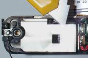 Do not attempt to bend or pull this up as the metal is very brittle. Run a blade around the outer edge to loosen the cement. Under NO circumstances should you attempt to clean the Beam Splitters which are the diagonal glasses in the assembly. These have a coating which both partially transmits and reflects
light. Contact with anything but a puff of air can remove the coating and destroy the camera's rangefinder capability. When replacing the metal cover on the assembly use a water based cement if possible. Model cement or crazy glue give off fumes that may deposit on the glass surfaces and make them slightly hazy.
Do not attempt to bend or pull this up as the metal is very brittle. Run a blade around the outer edge to loosen the cement. Under NO circumstances should you attempt to clean the Beam Splitters which are the diagonal glasses in the assembly. These have a coating which both partially transmits and reflects
light. Contact with anything but a puff of air can remove the coating and destroy the camera's rangefinder capability. When replacing the metal cover on the assembly use a water based cement if possible. Model cement or crazy glue give off fumes that may deposit on the glass surfaces and make them slightly hazy.
.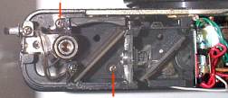
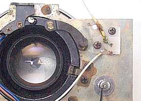
Access to the Finder Assembly:Only two screws hold the entire viewfinder / rangefinder assembly. These screws are indicated by the red arrows. Under no circumstances should any of the other screws in this unit be loosened, unless you are prepared to spend a huge amount of time getting the split image back in alignment. To the far left, you can see the screw that locks the position of the carry strap holder. To the right are the colour masks for the Over / Under exposure indicators of the GSN, but that in the Yashica Lynx IC models are attached to the battery holder. Through the use of an ingenious optical system, these exposure indicators appear as a
'heads up' display directly in front and to the top of your view through the finder.
Once you have access to the bottom of the rangefinder you can clean up and lubricate the mechanism that moves the mask. At this point it is worth mentioning that any lubrication that is applied anywhere on the camera must be free of water, which rules out household oils that do not contain water
dispersal agents. Use a high quality gun oil or BreaK Free CLP. If you don't have an Uzi around the house you may need to visit a sporting goods store to find this. I have found the hyperdermic syringe that came with an ink jet refill kit very useful for applying both WD40 and Oil. This is fortunate because I never was able to refill a cartridge with this stuff and get it to work, so at least I got something out of the deal. Before you replace the top plate, cut a thin slice of foam to a circle that is a bit larger than the
diameter of the hole in the case that the rewind shaft passes through. Cut a hole in the centre of this foam pad with a paper punch, and then push it in place over the shaft, to form a dust seal.
Getting the Frame Counter to reset: One of the related events that occurs when the foam light & dust seal starts to rot is that the gummy foam will prevent the frame counter from resetting to zero when the rear door is opened to load a new roll of film.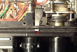
The image shows a portion of the rear track of the camera that normally holds the seal, with the both the foam and the top camera cover removed for clarity. The red arrow points to the tab that lies in the track that holds the foam. As you can see, the tab is a continuation of the lever that resets the frame counter.
A counter that fails to reset can usually be freed up by using a tooth pick to remove any sticky material preventing it from moving freely. This of course also indicates that the time for replacement of the foam seal has arrived. Complete details on the foam replacement follow.
Replacing the Loading Door Light Seals: Many of these cameras have sadly been brought to their knees by the failure of the light & dust gasket. This foam material eventually reverts to it's primordial state, turning this coal-tar derivative to a goo-ey mess. This can prevent the back cover from being opened.  Isopropyl Alcohol sold as "rubbing alcohol" in pharmacies, is an effective solvent of this messy stuff. Use a soft cloth dampened with this, and clean the edges around the door. The image is of an MG-1, one of the later models and Yashica had still not solved this problem. These trailing sticky bits of foam, or what's left of it, can get onto the back of your film as you shoot, and be transferred to the emulsion side as the film is rewound into the cassette The result will be to prevent that area of the image from being developed. It could also transfer to the processing solution and extend it's damage to other films in the bath, much like a virus.
Removal of the residue from the track around the camera body, can be done with patience. Moisten the area with a cotten bud dampened with Isopropyl Alcohol. Be sure the bud is not soaking. You don't want this solution to drip into the camera mechanism or onto the lens. After a couple of minutes begin to gently dig out the old foam using a flat tooth pick. Wipe it clean as you go along, re-applying the solvent from time to time. The fabric strip attached to the body at the location of the hinge should NOT be removed. Clean this gently. Protect the the back door from dust & light entry with black tape if you need to use the camera until you can get this replaced. On the GL there is no foam on the lower track of the camera body. A strip of what I believe to be velour, is attached the the bottom track in the door of this model. Since the only GL that I have come across has this sealer missing, and only the glue residue remains visible, this is a best guess on my part. This model has such a large overlap of the light trap at the hinge, that there is no foam seal between the door and the flange attached at the end of it.
What follows are complete illustrated instructions for making your own seals and installing them. If you prefer to use pre-cut seals, they are now offered by Jon Goodman. You can contact Jon at jgood21967@aol.com.
My attempts to cut bulk foam with an Exacto knife left a lot to be desired. In searching for a better solution I came across the left over roll of the "Frost King" weather-stripping [available from any hardware store, which I had applied some 30 years ago when the house was built. This dense black foam with a self adhesive backing was still in great shape. The foam is about 10mm wide by 5mm high, a perfect fit for the Yashicas when cut into 2mm wide strips. The strip shown is actually a precise cut but I was unable to prevent it from partly toppling over, so the size seems to vary.
To cut the strips I used a Fiskars 45mm rotary wheel fabric cutter. As a support, the Fiskars self healing mat worked out very well. Just apply a strip of the Frost King to the desired length on the cutting mat. Make use of the adhesive backing to hold it in place in a straight line. If the foam that you are working with has a very strong adhesive backing, it will help in seperating the strips if you first lay the foam on a piece of wax paper [found in most kitchens] and then place it on the mat to be cut. Use a plastic ruler as a guide for the cutting wheel. Place the wheel against the ruler onto the mat and draw it firmly toward and through the the foam. Do not start by pressing down onto the foam. Roll into it ! If you are using the slab foam, your ruler will likely be supported. If using the weather-stripping, place a second strip of foam alongside the one that you plan to cut so that the ruler can lie flat.
It is now fairly easy to press the foam into the track with a small curved wooden pusher or a coin if nothing else suitable is at hand. Note that you will see a small metal tab about one inch [25mm ] in from the right hand edge of the top track. This is the frame counter reset. Be sure not to damage this in cleaning out the track or replacing your new foam gasket, which should be continued under the tab. If you start from the right, cut the strip off just a little longer than the distance to the tab. You will then be able to push the end in under the tab with a flat toothpick. Push down gently on the tab to make sure it can compress the foam enough to activate the reset action of the frame counter. Continue on inserting the begining of the second piece of foam pushed tightly up against where the other piece left off. Due to the fact that this area is near the hinge of the door, that section will be better closed due to the relative angle of closure, so this is not all that fussy. Don't forget to replace the foam on the door itself, as shown in the image above. I used Elmers glue stick gel and it worked well keeping the foam in place and was less messy than most other alternatives to hold the foam to the door.
If your Lynx has a thin strip of velour at the hinge of the door, Diana Seeber came up with a brilliant idea. Visit your local Mini Lab and ask for an empty 35mm cassette. The lip that the film passes through is lined on both sides with exactly the right material that you need and may never find elsewhere.
Weather stripping is available at any hardware store. Be sure not to get the light weight grey stuff. The rotary fabric cutter is available at any sewing center or Walmart. Perhaps a neighbor who sews can lend you one with the board. Better yet, an experienced seamstress will probably be able to do a great job of cutting your strips for you in a flash.
Please visit the 'Rescue Guide' for the 'G' series on this site, much of the content applies to the Lynx. Just click on the link below. Thanks for visiting Yashica Guy.
Go to the Rescue Guide
If you have suggestions for improving the site, or a quick fix that you would
like to share,
Send us an eMail !
Go to the main Site Index
Entire contents of this web page are © 2000, 2011 Joe Marcel Wolff